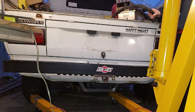
We cut and mitered the final section of square tubing for the motor mount, and bolted the full assembly to the frame rails. We discovered that the rails ware not rigid enough for this design. There was quite a bit of flex at the back end of the motor. Fortunately, the solution wasn't too bad.
A vertical section of square tube was welded to the motor mount arm, and bolted to the frame rail. Attaching in two places, at 90 degrees was a big improvement. The effective length of the arm that is cantilevered out to the motor is shortened substantially, and the load is spread across more of the frame rail.
Here is another view from underneath:
The view from the back isn't too bad either.
Once we get a coat of paint on that bare metal, it is going to look like the motor mount was original to the vehicle.
Tuesday, May 29, 2018
Sprite Battery - Rear Rack
These are the same cells that are used in the Nissan Leaf. Each module has 4 cells, wired 2 in series and 2 in parallel. The voltage of each module is 7.5 Volts, with a capacity of 65 Amp-hours. We have 48 modules available, provided we can find enough space in the car to fit them.
20 modules will fit in a rack behind the seats. Ideally we will be able to locate the rest of the cells in the front of the vehicle, under the hood, the maintain a decent weight distribution.
20 modules will fit in a rack behind the seats. Ideally we will be able to locate the rest of the cells in the front of the vehicle, under the hood, the maintain a decent weight distribution.
Monday, May 28, 2018
The Sprite Motor and Transmission Become One
We didn't make the groove in the adapter big enough to fit on the lip of the motor. It took a bit of hand filing to get the adapter to seat properly. In this case a bit is around 2 hours (at least it felt like two hours - might have been 45 minutes - I'm not sure because I've blocked it in my brain). You can see that we are only using 6 of the available 24 tapped holes. But don't install the bolts just yet.
The round adapter is not big enough to for the transmission bell housing, so we have this 12" x 24" x 0.5" (300 mm x 600 mm x 13 mm) plate that gets stacked on top of the round plate. We took care center up all of the plates, and use 1/4" (6 mm) pins so that the motor and transmission shafts are aligned. Error here will cause vibration and excessive wear or failure. Total error is on the order of 0.003" (75 microns). We made a collar that held the shafts aligned, and used transfer punches to mark where the transmission bolt holes and alignment pins should be located. These are the holes in the irregular pattern around the outer edges of the plate. Now is a good time to install the 6 motor bolts.
Looks good so far.
Next, the hub is installed on the motor shaft. That small hole on the hub had to be drilled and tapped to a larger size than the other three. The flywheel was mounted on the old gas engine crank shaft with two different sizes of bolts, so that the flywheel only bolts on in one orientation.
The flywheel gets bolted to the hub. The lower right bolt is slightly bigger than the other three bolts. The flywheel has three jobs with a gas motor - provide mass to smooth out rotational pulses from the explosions of the internal combustion cycle, provide a way for the starter motor to couple to the crank shaft and get the engine started (see the gear teeth around the circumference of the flywheel?), and it provides a surface for the clutch disk to grip. Electric motors deliver smooth power and can start up on their own, so we only need it for the clutch disk.
The pressure plate also has a surface to grip the other side of the clutch disk. It has a bunch of springs and a mechanism to release the clutch disk pressure when you press the clutch pedal.
Now we slide the transmission and motor together, and on the second attempt, everything fit together as we expected the first time. It turns out we didn't drill the center hole in the hub deep enough for the length of the transmission shaft. But after scratching our heads for a while, we got it all figured out.
This motor and transmission need to end up in that Sprite. Easier said than done...
You just tip the nose of the transmission down, and slide the engine hoist that way, and rotate the motor to clear the hood latch. It doesn't help that the engine hoist base is too wide to slide between the front wheels (or the Sprite is too narrow). Something is not quite fitting correctly. Time for some more head scratching.
That looks really good. Like it was meant to be.
The gear selector lines up exactly where it is supposed to go.
Subscribe to:
Comments (Atom)


