Sunday, February 10, 2019

Motor Mount for the Sprite

This is a neat trick. After the motor and transmission were joined and placed into the engine compartment, the motor just floats in the engine bay. 


The trick is we used a really secure stack of lumber scraps to position the transmission in the same alignment as when it mated to a gas engine.  We defined the correct position of the motor based on the alignment of the transmission.

There are three M12 bolts on the front of this motor.  Trying to purchase the correct bolts, I learned that there are three pitches of screw threads for metric bolts.  This motor takes the extra fine pitch, for maximum bolt shear strength. 

This structure matches the bolt pattern on the front of the motor.  Don't worry, we come back and give it full welds after we check for fitment.

And it does fit. These bolts were merely fine thread, and won't go in any more than a quarter turn.

This view from above shows that the gap is closing, and more importantly we have a weldable surface to extend the structure.
 

Ears are welded on and reinforced. The ears will serve as a mounting surface for a pair of rubber dampers. Even through electric motors have far less vibration and rumble than the gas engine, a rigid mount to the vehicle's frame is not desirable.

Here the rubber is present, as well as a structure that we made to reach the stock motor mounting holes in the car.  We did this because drilling the fewest number of holes in the car is desirable, and the existing mount location is already engineered to be strong.
Here is the bottom view of the motor mounting bracket.
The fit looks good.  And we have the proper M12 x 1.25 exrta fine pitch bolts installed.

Painting the Doka Racks

It is far past time for a project update. Paul and I have been working away, making progress, and taking pictures most Tuesday nights and Sundays for the last year. Now that the weather is cold, and we can't spend long periods of time outside, I have an opportunity to catch up on the blog.

We used this touch up spray gun from Harbor Freight to apply primer and paint to all of the angle iron battery racks we have been fabricating.  There are probably better spray guns out there, but this worked really well.  Much better than rattle cans.  My 5 gallon air compressor was just barely able to keep up.
 
Prep work is important.  Paint will magnify and enhance even minor imperfections - such as paint that is flaking off.  We can't neglect to remove rust, weld slag, oil, or mill scale from the metal stock.  This is Paul working, while I watched and filmed.  The rate is sped up 8X.  Too bad we can work that fast in real time.

The primer is a deep brown color.  This will help get full coverage when we spray the black top coat.  Thin areas will be obvious, because they won't look black.  We are using cheap plastic drop cloths because we aren't trying to paint Paul's patio.

We tried to save time by hanging the small parts, so that we could paint the entire part at one time, instead of painting one side, and waiting for them to dry before turning them over for a coat on the back.  The spray from the gun tends to knock the parts around and get them spinning, which sounds cool, but isn't if you're trying to get a decent looking paint job.  Two wires, next time.

The rack looks good in black.  This is under the rear passenger bench seat, and will house 48 cells.

The cells are wedged snuggly and securely into their new home.

The racks under the truck bed are on sliders and they look really good.  It looks like there is a lot of room in this space, but it was ridiculously difficult to turn a wrench inside the compartment.  Awkward angles and no good line of sight on the bolt location for securing the rack to the truck made for a good challenge.
 But it was worth it.  Look at those battery racks.

Monday, June 18, 2018

Doka Battery Rack, Part 2

Under the bed of the Doka, and behind the cab is a rather large storage space that is perfect for half of the battery cells.
The space is rather deep given the modest opening, so to improve accessibility, the battery racks will be mounted on ball bearing sliders.  The gussets at the top left corner of the space interfere with the racks.  We have to cut notches for clearance, and weld in some structure to keep the bed support strong.
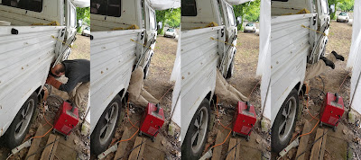
Someone has to go in there to weld the back side of the brackets.  This is Paul.  Watch Paul disappear.
Here the gusset is notched and reinforced.
Here we are aligning the rails on the battery racks.  If these aren't parallel, the slides will bind and not open properly.
The rack is closed.
The rack is open.
The rack is open in the car.  (Apologies the Dr. Seuss and we will have to order some more flat bar to finish up the rest of the right rack.)

Sprite Motor Mount, Part 1

After we slid the motor and transmission in, we had to figure out the bolt sizes of the four transmission cross brace.  It is a job that would have been much easier before we put the motor into the car.  But the internet is a wonderful resource and we were able to narrow it down to 1/4 inch, 5/16ths and 3/8 imperial fine thread.  Here you can see the shifter port coming through the tunnel, and the shiny bit on the vertical wall of the tunnel is a 5/16" x 1" fine thread bolt.
 Two more 3/8" x 3.5" fine thread bolts are installed from under the car, just behind this stack of wood.  The wood is holding the motor in the correct position so that we can take measurements and determine how to fabricate a front motor mount.
 The space is tight, so this is the best shot I could get of the motor face.  There are 3 M10x1.5 mm  tapped holes that can be used to mount the Remy HVH250.
 We start out with two lengths of 1.5" x 1/8" flat bar (38 mm x 3 mm).   Using the motor face as a jig, we grind the parts until all three holes are aligned to the motor face...
...and then weld the parts together. 
Flat bar will not be substantial enough on its own, so the structure is built up with some square tube.
 All the seams are welded.
 Here the mount is shown in position.   We will need to get some shorter bolts.
Up next for the motor mount is to extend square tubing out to the mounting points of the car, and connect to the rubber mounts.

Doka Controller Rack

 We made a little rack for the controller.  There is not much to it: a few lengths of angle iron, some welding, and for the final mounting we will add in some paint and rubber mounts to isolate the controller from road vibration.

Tuesday, May 29, 2018

Motor Mount for the Doka, Part 2

We cut and mitered the final section of square tubing for the motor mount, and bolted the full assembly to the frame rails.  We discovered that the rails ware not rigid enough for this design.  There was quite a bit of flex at the back end of the motor.  Fortunately, the solution wasn't too bad.
A vertical section of square tube was welded to the motor mount arm, and bolted to the frame rail.  Attaching in two places, at 90 degrees was a big improvement.  The effective length of the arm that is cantilevered out to the motor is shortened substantially, and the load is spread across more of the frame rail. 

Here is another view from underneath:
The view from the back isn't too bad either.
Once we get a coat of paint on that bare metal, it is going to look like the motor mount was original to the vehicle.

Sprite Battery - Rear Rack

These are the same cells that are used in the Nissan Leaf.  Each module has 4 cells, wired 2 in series and 2 in parallel.  The voltage of each module is 7.5 Volts, with a capacity of 65 Amp-hours.  We have 48 modules available, provided we can find enough space in the car to fit them.
 
20 modules will fit in a rack behind the seats.  Ideally we will be able to locate the rest of the cells in the front of the vehicle, under the hood, the maintain a decent weight distribution.

Monday, May 28, 2018

The Sprite Motor and Transmission Become One

In today’s episode we take the adapter plate that we made in this blog post and the hub that we made in this post to join the motor with the transmission.  Here is the drive end of the electric motor.  Just inside the ring of 24 tapped holes, there is a lip.  This lip is used to align the motor to what ever you are bolting to the motor.  We won't need all of the tapped holes.  Those holes represent a lot of mounting options.
We didn't make the groove in the adapter big enough to fit on the lip of the motor.  It took a bit of hand filing to get the adapter to seat properly.  In this case a bit is around 2 hours (at least it felt like two hours - might have been 45 minutes - I'm not sure because I've blocked it in my brain).  You can see that we are only using 6 of the available 24 tapped holes.  But don't install the bolts just yet.

The round adapter is not big enough to for the transmission bell housing, so we have this 12" x 24" x 0.5" (300 mm x 600 mm x 13 mm) plate that gets stacked on top of the round plate.  We took care center up all of the plates, and use 1/4" (6 mm) pins so that the motor and transmission shafts are aligned.  Error here will cause vibration and excessive wear or failure.  Total error is on the order of 0.003" (75 microns).  We made a collar that held the shafts aligned, and used transfer punches to mark where the transmission bolt holes and alignment pins should be located.  These are the holes in the irregular pattern around the outer edges of the plate.  Now is a good time to install the 6 motor bolts. 
 Looks good so far.
 Next, the hub is installed on the motor shaft.  That small hole on the hub had to be drilled and tapped to a larger size than the other three.  The flywheel was mounted on the old gas engine crank shaft with two different sizes of bolts, so that the flywheel only bolts on in one orientation.
 The flywheel gets bolted to the hub.  The lower right bolt is slightly bigger than the other three bolts.  The flywheel has three jobs with a gas motor - provide mass to smooth out rotational pulses from the explosions of the internal combustion cycle, provide a way for the starter motor to couple to the crank shaft and get the engine started (see the gear teeth around the circumference of the flywheel?), and it provides a surface for the clutch disk to grip.  Electric motors deliver smooth power and can start up on their own, so we only need it for the clutch disk.
 The pressure plate also has a surface to grip the other side of the clutch disk.  It has a bunch of springs and a mechanism to release the clutch disk pressure when you press the clutch pedal.
 Now we slide the transmission and motor together, and on the second attempt, everything fit together as we expected the first time.  It turns out we didn't drill the center hole in the hub deep enough for the length of the transmission shaft.   But after scratching our heads for a while, we got it all figured out.
This motor and transmission need to end up in that Sprite.  Easier said than done...
You just tip the nose of the transmission down, and slide the engine hoist that way, and rotate the motor to clear the hood latch.  It doesn't help that the engine hoist base is too wide to slide between the front wheels (or the Sprite is too narrow).  Something is not quite fitting correctly.  Time for some more head scratching.

We quickly identified the issue.  The lower corners of the adapter plate are hitting the frame rails of the car.  It's nothing that can't be solved with a little time with the saws-all (reciprocating saw).
 That looks really good.  Like it was meant to be.
The gear selector lines up exactly where it is supposed to go.